
Electronics for medical implants present major technical challenges to designers relating to packaging, power and miniaturisation. The reason is that many medical products are implanted where the space envelope is limited, the position is critical and available power is restricted. However, this is not always the case and designers need to be very careful when producing the specification that it satisfies the technical requirements, without imposing unnecessary constraints.
In addition, it is essential that the medical electronics meet the necessary competent authority, which is the MHRA in the UK. As regulatory requirements are stringent for any implant, the complexity of the implant electronics is often kept to a minimum and ‘passive’ when possible. The associated body-worn electronics generally have the built-in intelligence, which significantly reduces the level of risk for the implant system.
Go deeper with GlobalData

Discover B2B Marketing That Performs
Combine business intelligence and editorial excellence to reach engaged professionals across 36 leading media platforms.
For on-the-body medical devices, space, packaging and power may be less of an issue and the approvals route is also significantly easier. For example, some on-the-body monitoring equipment only requires CE marking.
Healthy Aims
One EC-funded project, Healthy Aims, set its goals to develop a number of different medical devices over the four-and-a-half-year project duration. Each device comprised electronic circuitry integrated into a system module, some of which are implanted, the rest on the body. Each had their own specific system requirement, which incorporated the electronics specification. The systems that were developed included:
- human body motion system
- glaucoma sensor
- urodynamics catheter sensor
- intra-cranial pressure (ICP) sensor
- FES for upper limb stimulation
- retina implant.
Human body motion system
This on-the-body system had to be small and light enough not to affect the limb motion and have sufficient power to be able to complete the required test procedure; activity monitoring over a 24-hour period, or gait monitoring over a six-hour period. A weight of 50g and volume of 80 x 30 x 15mm was specified as acceptable for both. This could be considered as the simplest specification of all of the devices developed but still it required advancements beyond the existing state-of-the-art in terms of packaging.
Gait monitoring was more stringent, as six degrees of freedom had to be monitored at a frequency of 100Hz. The system solution included a rechargeable battery and a USB interface for charging. There was also an SD card for data storage, a precision time clock and a synchronisation facility so that a number of inertial measurement units (IMUs) could be synchronised together.
The sensors, a three-axis accelerometer plus three single-axis gyros, together with a microcontroller and SD card and associated electronics, were mounted onto a multi-layer flexi-rigid PCB board. A simple start/stop button was provided to improve ease of use. With the advancement of memory storage capability on SD cards data can be stored for many hundreds of hours without downloading to a PC if necessary. This enables the user to carry out tests anywhere, with no need to be close to a PC.
This sensor module has now been CE marked by ETB and successfully validated for monitoring joint angles on humans by the University of Salford (USAL). For these trials USAL had to write a trials protocol and submit this to the local ethics committee for approval, which took around three months in total. This system is now being used in clinical trials in an orthopaedic application.
Glaucoma sensor
An on-the-body system that presented considerable challenges in terms of miniaturisation was the glaucoma sensor. The sensor system had to be integrated into a standard contact lens, fitting exactly to the curvature of the eyeball in order that minute changes in the radius of curvature resulting from changes in ultra-ocular pressure could be monitored. In addition, the sensor system had to be wireless, communicating to the reader module for subsequent analysis. This meant that an antenna also had to be integrated into the contact lens.
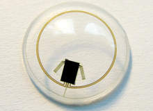
The final sensor system solution has an ASIC thinned to 50µm, with gold stud bumping directly on to a flexible polyimide substrate. The ASIC combines the power and data transmission circuitry running at 27.4MHz with the drive and detection circuitry for the strain gauge. The active and passive strain gauges and antenna are fabricated on the same flexible substrate as the ASIC. The complete flexi-circuit, shown in Figure 1 and 2, is 100µm thick and is moulded into a silicone lens.
The power and data circuitry is provided by the reader integrated into a pair of spectacles, with the system designed to minimise the transmission loss.
The complete assembly had to meet with the requirements of the Medical Device Directive, both in terms of the biocompatibility of the sensor module which is mounted directly onto the eye and also the power transmission to the eye. The contact lens was encapsulated in silicone, which is an approved biocompatible material. The ASIC was designed to ensure that the power transmission at 27.4MHz remained below the acceptable power threshold.
In order to carry out clinical trials the system and a protocol had to be defined and submitted to the local ethics committee for approval. Having obtained approval the system was tested on five healthy volunteers and in all cases an induced change in intra-ocular pressure was correctly detected. Clinical trials will continue through 2008 to ascertain the clinical efficacy of the system on glaucoma patients.
Retina implant
The retina implant was perhaps the most challenging implant electronic system, requiring a high-density individually addressable electrode array which is compliant enough to fix to the retina and make contact with the ganglian cells. A number of design options were considered by the ophthalmologist using dummy implants to ensure that the eye structure would not be damaged by the implant. The final design housed the electronics in the eye socket, with a small incision to pass the electrode array into the eye.
A digital image is obtained from a video camera inserted in a visual processor designed as a pair of spectacles.
This signal is transmitted via a wire to a pocket processor worn on the waist, with minimal size and weight constraints. A complex algorithm developed by IMI translates the image into a stimulation pattern in the processor. This has enough charge to power the electronics in the processor and spectacles all day and is charged overnight.
This stimulation pattern is transmitted back to the spectacles and transmitted to the implanted electronics at infrared, as this is most suitable for the high data rates required for real-time images. This stimulation pulse pattern is then fed to an ASIC where the charge current pattern for each electrode is set and passed to the individual electrodes, which subsequently puts a charge on the ganglian cells.
The charge pulse is transmitted to the brain where it is translated into an image. The implant incorporates the ASIC and an IR receiver. These are mounted onto a flexible circuit. At the other end of the implant is the electrode array. The electrode array used in patient trials was tacked to the back of the eye to ensure that the electrodes made contact with the ganglian cells.
Obtaining approval for clinical trials is an extremely complex process as the retina implant remains in the body for a number of years. The entire implant, except for the electrode area, has to be hermetically sealed with a biocompatible material and this has to be demonstrated before approvals for the trials can be obtained.
In addition, the ethics committee has to approve the choice of volunteers and the trials protocol. It must be noted that the regulatory procedures takes typically 12 months for an implant, resulting in 12-month elapsed time between design freeze and patient trials starting. In this project the trials started in year four and by mid-2008 three blind volunteers had received the first implants and in all cases visual perception had been realised.
Suitable designs
Each of these three examples of medical electronics were designed, manufactured and taken through into human clinical trials. This is essential if the product is to obtain CE marking and be sold commercially. Designers must consider the application constraints and the Medical Device Directive requirements.
The first, the human motion monitoring system, had the least challenging specification in terms of size, power and weight requirements. As such, only a multi-layer flexi-rigid PCB and BGA components were required. It also had the easiest route to clinical trials, needing only ethics approval.
For the glaucoma sensor the packaging requirement was particularly demanding to ensure that the contact lens was sufficiently compliant to take the curvature of the eyeball. The system solution incorporated a thinned ASIC mounted onto a flexible substrate.
The approval process to go to clinical trials required both approval from the Medical Device Directive and an ethics committee.
For the retina implant the main challenge was to produce a high-density array and associated electronics to produce sufficient charge density on the electrodes to stimulate the ganglian cells. Similar packaging methods to the glaucoma sensor were utilised, keeping it sufficiently compact to fit into the eyeball cavity.
The wireless transmissions were kept within the safe limits. Approval was the hardest of the three to obtain as long-term biocompatibility trials had to be carried out, as well as all the other tests required by the Medical Device Directive. The recruitment process once ethics approval was obtained was also complex as it involved blind volunteers receiving a new implant.
A tiny future
New medical implants and on-the-body diagnostic equipment will continue to be developed as micro and nano electronics, plus micro-packaging techniques become more widely available. It is anticipated that further developments in interconnects, one of the limitations identified in the Healthy Aims project, will bring the performance of these systems closer to that which the human can achieve.
