
We have only performed non-destructive analysis on the fractured CSLP pieces to determine only the fracture mode. We performed initial low magnification stereomicroscope examination on both fracture pieces of the locking plate at 50X magnification.
One half of the fractured locking plate piece was examined in the Scanning Electron Microscope (SEM) to determine the fracture mode and crack initiation areas.
Recommended Buyers Guides
The fine features on the fracture are analysed to determine the fracture mode (for example, fatigue, overload, and embrittlement).
Results
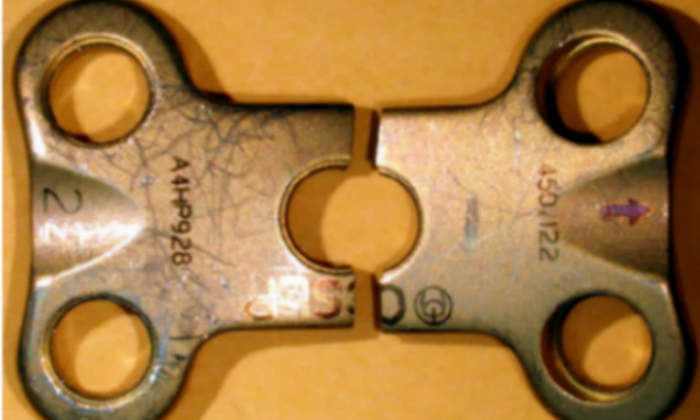
An overall view of the fractured CSLP is shown in Figure 1. Note that the piece fractured in two halves. This view is from the top surface of the plate on which the identification markings were present.
Note that adjacent to the center hole, the writing CSLP is present and the piece fractured through the letter “C”.
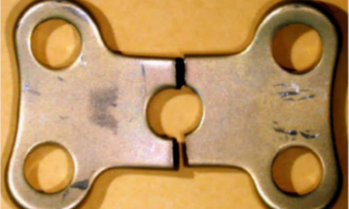
An overall view of the opposite surface of the CSLP is presented in Figure 2.
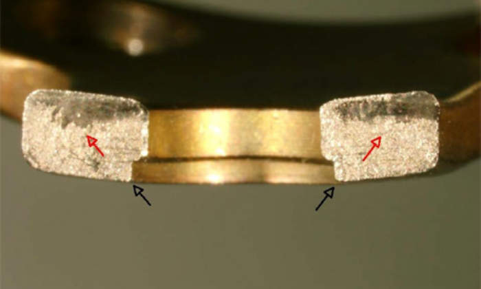
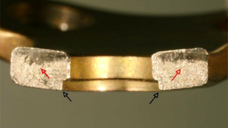
An overall view of the fracture surfaces of the left-hand side piece in Figure 1 is presented in Figure 3. The two black arrows at the corners point to the approximate crack initiation areas. The red arrows point to the overall crack propagation directions on the surfaces.
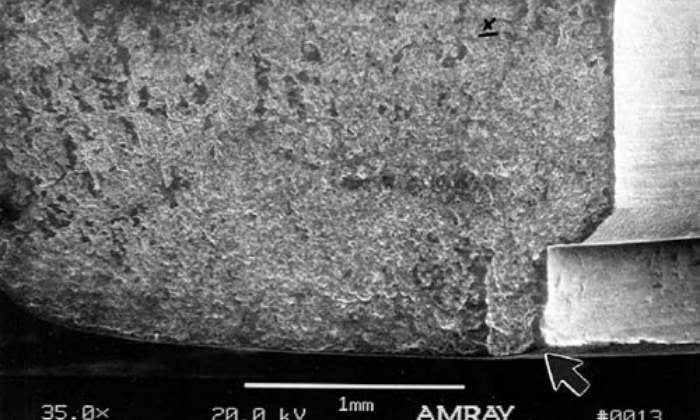
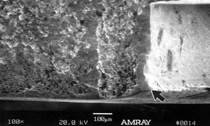
An SEM view of the fracture surface on the left-hand side in Figure 3 is displayed in Figure 4. The arrow points to the crack origin area at the corner. Note that there were some semielliptical shaped or clam-shaped markings on the fracture which emanated from the origin. These markings are called “beach marks” and are typically associated with a progressive type of fracture or with a fracture which progresses with time. These are macrocrack arrest markings during the progression of the crack.
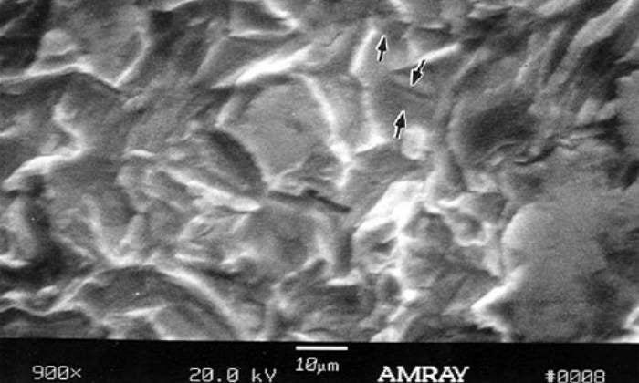
A higher magnification view of the origin area is presented in Figure 5, arrow. Note that there was post-fracture damage present right at the corner and on some areas of the fracture which is evidenced by the smooth appearing areas. A higher magnification view of the area marked “x” in Figure 4 is presented in Figure 6. The small arrows on the fracture surface identified some fatigue striation type parallel markings which indicate that the crack after initiation progressed, most likely, under cyclic loading. These are microcrack arrest markings. The overall features associated with the fracture can be typically related to the fatigue failure of a titanium alloy. There were many secondary microcracks observed which is also associated with fatigue failure of titanium alloys.
Findings and discussion
Our non-destructive fracture mode analysis of the failed Cervical Spine Locking Plate (CSLP) indicated that the fracture initiated on the opposite sides of the middle hole area of the plate at the corner of the hole and top surface (the surface which is towards the outside of the spine when assembled). It appeared that after initiation, the cracks propagated in a progressive manner with cyclic type loading or intermittent loading condition.
Typically fatigue failures of unalloyed titanium depends on grain size, interstitial contents, degree of cold work, surface finish, etc. There can be many chemical and microstructural contributions also.